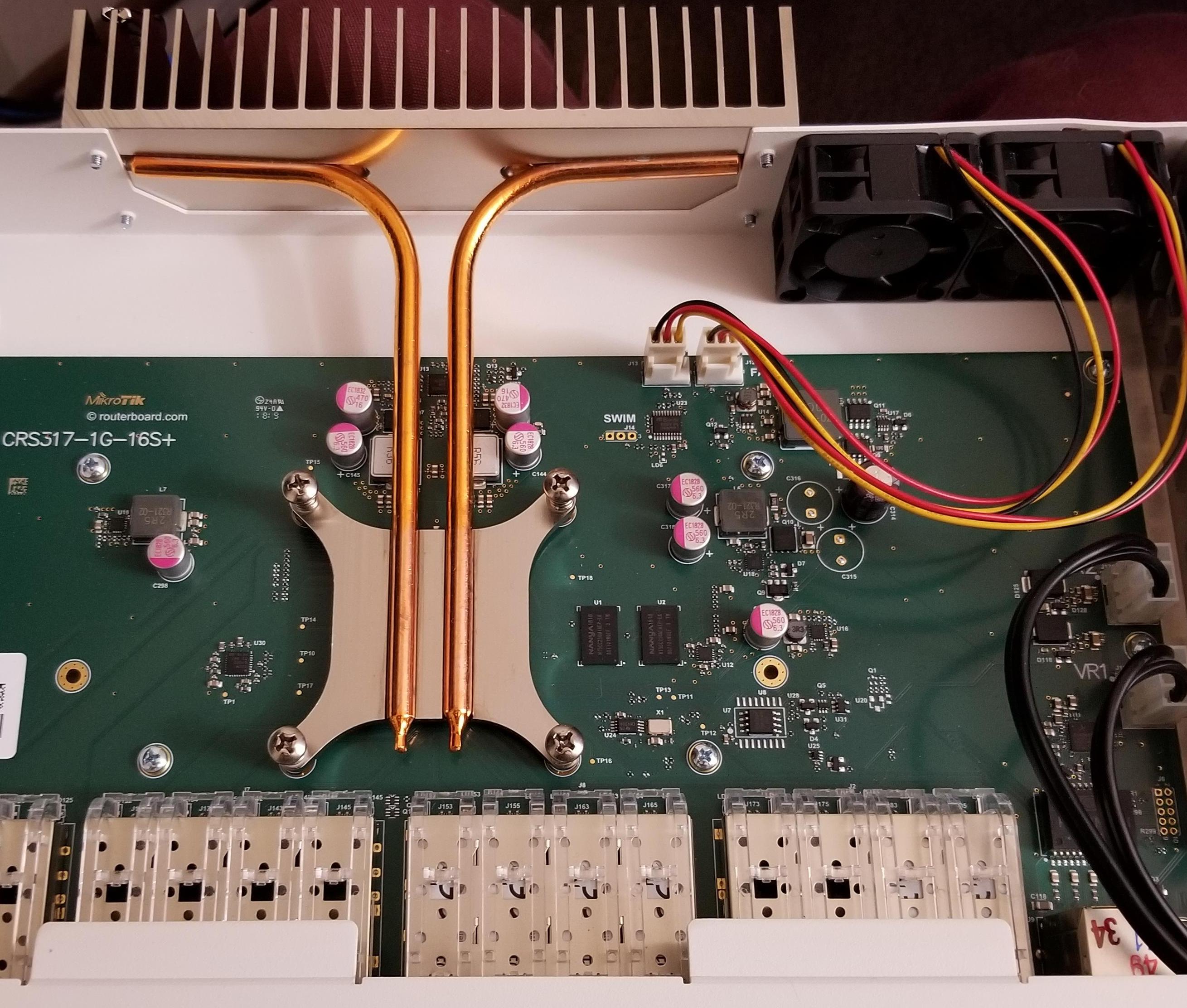
While upgrading to 10GbE for my network storage array, I set up this MikroTik CRS317-1G-16S+RM as my primary switch. The network was nice and fast, but the stock fans were very loud under load (clocked up to 74dB at the back). My network rack lives in my office, so I decided to print an adapter and mount a pair of larger, but much quieter 60mm fans.
The adapter should fit in place of any similar pair of 40mm fans, on other MikroTik devices and elsewhere, and can easily be tweaked to fit even larger fans.
Fans
I looked into replacing them with similar 40mm internal fans, but the 40mm profile is limiting and generally comes in either low-RPM and low-CFM or high-RPM and high-dB variants. Looking up a size at 60mm fans, the noise level remains low but CFM increases dramatically. I settled on these:
Very rough math suggested that a pair of them would move almost twice as much air as the original fans (which were incompletely labeled, and I didn’t account for the adapter). Unfortunately, the switch has a large heatsink on the back that would prevent mounting the fans directly, and 60mm fans are too tall to fit in a single rack unit.
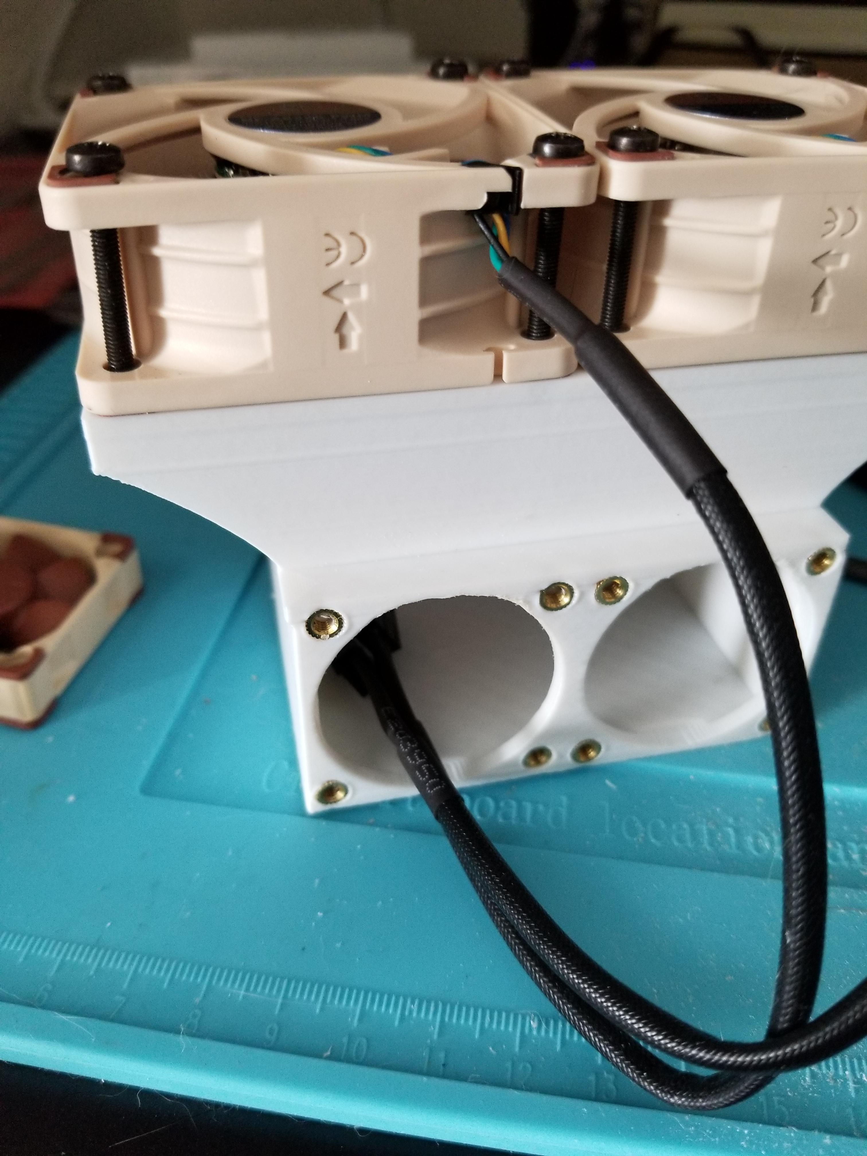
Case & Adapter
The MikroTik rackmount case is quite sleak and tidy looking, but doesn’t have room for a pair of vertical 60mm fans and I didn’t want to cut into it much - drilling a hole for fan cables was the most I wanted to damage the case.
It was not difficult to design a small adapter for the fans, but I had to make it fit around the substantial heatsink on the back of the switch. After sketching a few designs, I settled on a 90° curve upward:
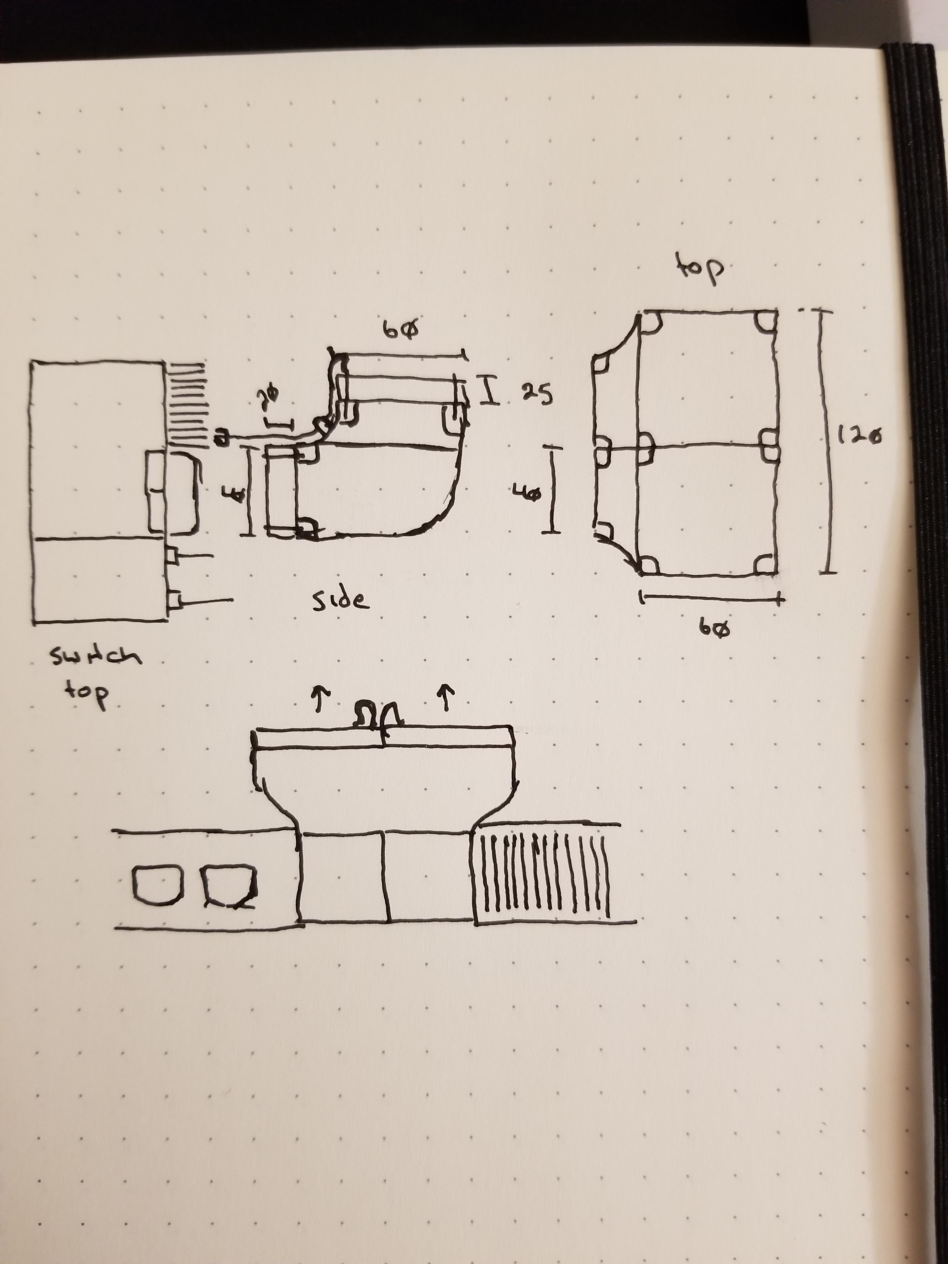
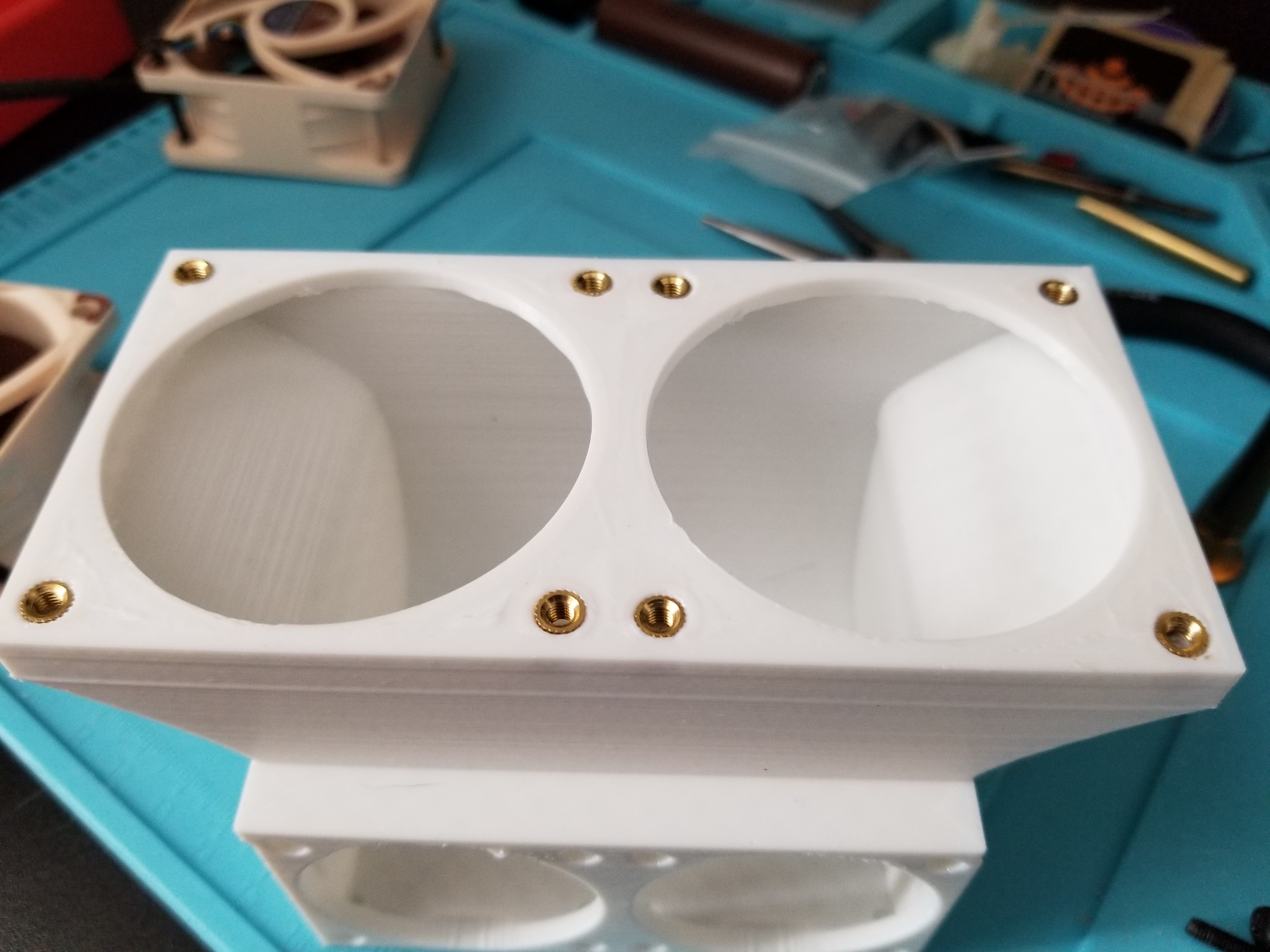
With a little bit of work in Onshape, I put together an adapter with a smooth interior that would fit around the heatsink:
Heat Set Inserts
Having read about them a few days before on Hackaday (THREADING 3D PRINTED PARTS: HOW TO USE HEAT-SET INSERTS), I wanted to use heat-set inserts to thread the adapter and mount the fans properly, to avoid introducing vibrations. After a little bit of practice on the prototype print and some adjustments, all the holes were threaded and only a few were crooked:
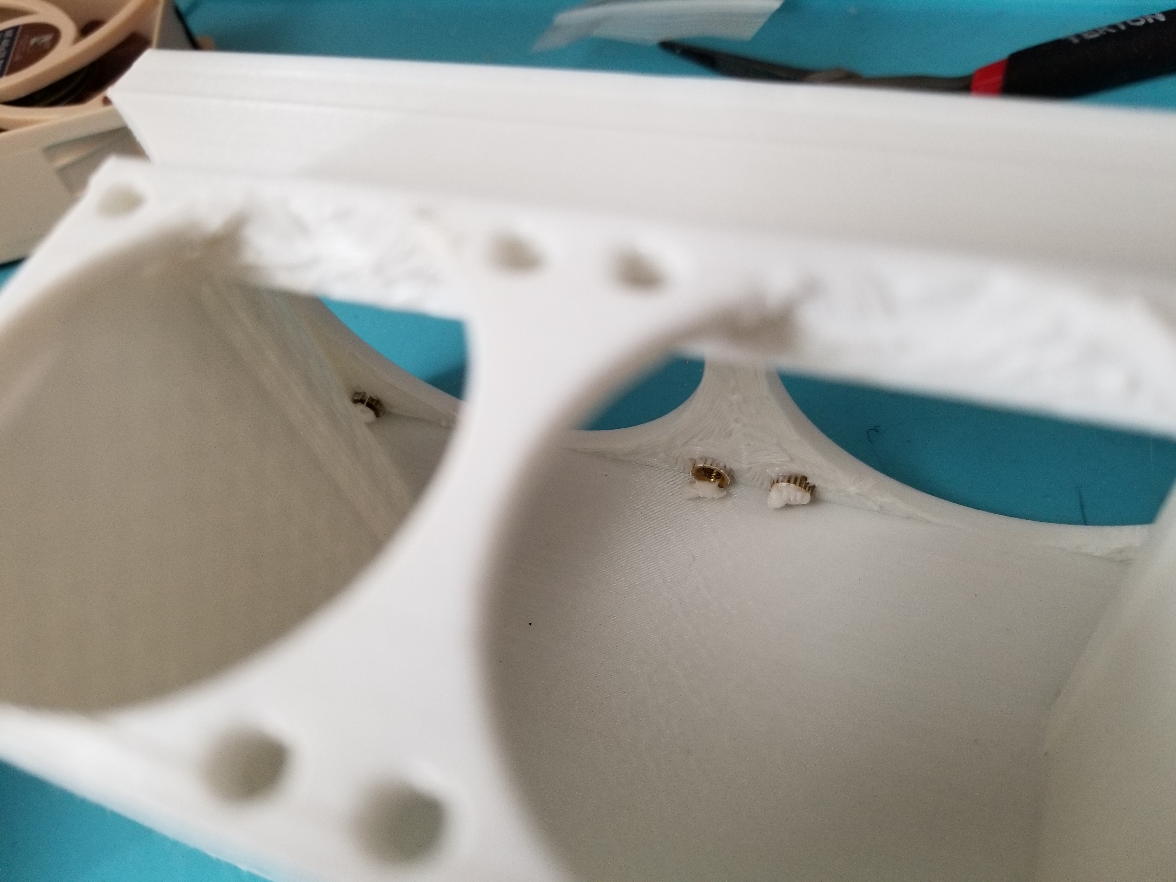
Each insert took a few seconds to heat up, then sunk into the plastic under the weight of my soldering iron and hand. Despite my best effort to use a light touch, a few managed to slip through, which prevented the inner knurling from getting a grip on the plastic:
Making the walls thicker would have helped, but if you make them too thick, the extra will melt into the back of the insert and clog it. I cleaned out a few clogs with careful use of heat and tweezers, and adjusted the inserts to line up with the fan bolts. The bolts were large enough to hold without a washer, and the fans have rubber feet of their own:
One of the inserts was clogged and/or had a poor grip, which caused it to break loose and start spinning with the bolt. For later prints, I’ve tried some combination of reinforcing the walls, adding inner caps, and using shorter inserts to improve grip. The most common problem has been extra plastic clogging the threads.
Results
This design fit nicely with a smaller EdgeRouter stacked on top, then later with the MikroTik switch rack mounted under a similarly-sized router:

After replacing the fans, I took rough noise measurements with this decibel meter from a few places near the switch. Compared to the original fans, the replacement was quite effective at reducing noise:
| Fans | Avg Temp C | Max dB at front vent | Max dB at back fans |
|---|---|---|---|
| 40mm stock | 72 | 70 | 74 |
| 60mm Noctua | 70* | 56 | 58 |
While testing the new fans, I found a note in the S+RJ10 documentation suggesting they be installed in every other SPF+ slot, which decreased the temperature a further 2C.
The new fans did not cool the switch much better than stock, but they did reduce noise considerably - my desktop is louder under load and the CR-10 easily drowns both out.