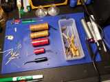
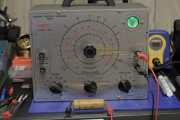
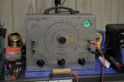
This Eico 950B was the first piece of vacuum tube test equipment that I recapped. Most of the capacitors look like they were original, so based on the date code, it was working for a solid 65 years until I got ahold of it - from 1957 to 2022. It does work again, and is much more accurate than when I started, so I’m pleased with the results so far. There are a few modern safety features as well, including a safety capacitor, fuse, and grounded line cord.
High voltages are present within vacuum tube equipment and often extend out to the chassis. DO NOT attempt to operate or repair vacuum tube equipment unless you know what you are doing, have proper safety equipment, and someone else is present. Capacitors can retain a lethal charge for a very long time and need to be safely discharged. Do not try this at home.
Danger: High voltage can be fatal!
Repairs
The Eico 950B is a popular vacuum tube capacitor tester, with quite a few good articles written about restoring them:
- https://antiqueradio.org/EICO950BBridge.htm
- https://lazyelectrons.wordpress.com/2017/11/10/eico-950b-repair-restoration/
- https://people.ohio.edu/postr/bapix/CapChkr2.htm
The wealth of existing literature encouraged me to pick one up from eBay and fully recap it, saving all of the testing for the end. It was an interesting choice and not necessarily the method I would recommend. Testing each component after you replace it takes a while, but you can take before and after reading with an LCR meter - even if there are other components in parallel, if you replaced the original part with a similar value, the final reading should also be similar. Be careful of the testing frequency, that can really impact the readings for some capacitors.
Most of the linked articles write about their difficulty finding an 8uF, 525V electrolytic capacitor. I ended up staying within the Vishay family and used a pair of 20uF, 350V parts from the TVA ATOM range, with a 470K, 1W resistor across each. I picked up a few extras and selected the lowest values, both in the 18-19uF range, resulting in a 9.13uF capacitor that should be good for at least 600V.
After replacing all of the passives, even the single precision mica, the meter is pretty accurate. Some of these test components have drifted from their original values, but the reading looks to be within ±2-3% of what the DER DE-5000 reports. While taking pictures, I was interrupted by a creature that also stores energy in a static electric field.
This tester can find failures in some high value, high voltage capacitors, the kind you don’t want to touch. When a capacitor is on the verge of failing at lower voltage, like the 25 MFD wax shown in the photos, the eye will wobble and open slowly, then stop opening when you reach the failure voltage. Since this applies voltage to the capacitor, make sure to discharge them after testing and reduce the voltage dial slowly, not all at once.
Replacement Parts Installed
| Part | Schematic | Part Used | Replacement | Original | Capacitor Test | Notes |
|---|---|---|---|---|---|---|
| C1 | 8 MFD 525V, electrolytic | Vishay TVA1608-E3, 20uF 350V | 9.132uF | 7.6-10.8 | some leakage over 450V | continuously climbed on the DER meter, replacement is two in series |
| C2 | 200 MMFD, precision mica | Vishay/BC Components BFC237525201, 200pF 1000V | 202.7 pF | not tested | within original tolerance, replaced for completeness | |
| C3 | .02 MFD, precision wax | Panasonic ECW-F6203HLB, 0.2uF 630V | 21.91 nF | leaks around 271V | ||
| C4 | 2 MFD, precision wax | Panasonic ECW-F4205JL, 2uF 400V | 2.145 uF | good to rating | very waxy, had to scrape off a few layers to see the markings | |
| C5 | .01 MFD 400V, wax | Vishay/BC Components BFC237522103, 10000pF 1000V | 11.426 nF | some leakage over 400V | tested after removal, could have been C6 or C7 | |
| C6 | .01 MFD 400V, wax | Vishay/BC Components BFC237522103, 10000pF 1000V | 14.396 nF | leaks around 170V | tested after removal, could have been C5 or C7 | |
| C7 | .01 MFD 400V, wax | Vishay/BC Components VY2103M63Y5UG63V0, 0.01uF X1Y2 | 12.456 nF | leaks around 233V | replaced with safety cap, tested after removal | |
| C8 | .25 MFD 600V, wax | Vishay/Roederstein MKP1839433084HQ, 330nF 850V | 293.6 nF | leaks around 211V | ||
| C9 | 4 MFD 250V, electrolytic | Vishay/Sprague TVA1703, 5uF 450V | 5.518uF | 4.253 uF | good to rating | |
| R1 | 500 ohm, 4W | Vishay/Dale RS005500R0FE12, 500 ohms 5W 1% | 483.4 ohm | |||
| R2 | 250K, 1/2W, 1% | Vishay/Dale CMF55249K00BEEB, 249K 1/2W .1% | 253.1K ohm | |||
| R3 | 1M, 1/2W | Vishay/Dale CMF551M0000FHEK, 1M ohms 1/2W 1% | 1.051M ohm | |||
| R4 | 20 ohm, 1/2W, 1% | Vishay/Dale CMF6020R000BHEB, 20 ohms 1W .1% | 20.21 ohm | |||
| R5 | 2K ohm, 1/2W, 1% | Vishay/Dale CMF602K0000BEBF, 2K ohms 1W .1% | 2.080K ohm | |||
| R6 | 200K ohm, 1/2W, 1% | Vishay/Dale CMF55200K00BHEB, 200K ohms 1W .1% | 200.8K ohm | |||
| R7 | 3.3K ohm, 1W | Vishay/Dale RS02B3K300FE12, 3.3K ohms 3W 1% | 3.450K ohm | |||
| R8 | 68K ohm, 1W | Vishay/Dale RS00568K00FB12, 68K ohms 5W 1% | 75.10K ohm | N/A | original was +10.3% out | |
| R9 | 270K ohm, 1/2W | Vishay/Dale CMF07270K00GKR6, 270K 1/2W 2% | 278.1K ohm | |||
| R10 | 10M ohm, 1/2W | Vishay/Dale CMF5510M000FKEB, 10M ohms 1/2W 1% | 9.87M ohm | |||
| R11 | 2.2K ohm, 1W | Vishay/Dale RS02B2K200FE12, 2.2K ohms 3W 1% | 2.207K ohm | |||
| R12 | 470K ohm, 1/2W | Vishay/Dale CMF60470K00FHEK, 470K ohms 1W 1% | 433.4K ohm | N/A | original was -7.9% out |
I measured all of the replacement components while installing them, but cannot find notes on those values, and had to remeasure the capacitors in-circuit after the rebuild was complete.
Original Parts Retained
| Component | Schematic | Measured |
|---|---|---|
| P1 | 10K | 10.748K ohm |
| P2 | 1K, with SPST | 1.073K ohm |
| P3 | 100K, 4W | 96.69K ohm |
The potentiometers all read within tolerance with the leads cut, so I left those in place and reattached them with some soft silicone wire. The tubes appear to be working and I don’t have a way to test them out of circuit, same with the transformer. There are no diodes or other components, this is a very simple circuit with very high voltage.


