This is the second piece of magic eye tube test gear that I’ve recapped so far, and probably should have been the first, because it had a fraction of the components compared to the Eico 950B.
High voltages are present within vacuum tube equipment and often extend out to the chassis. DO NOT attempt to operate or repair vacuum tube equipment unless you know what you are doing, have proper safety equipment, and someone else is present. Capacitors can retain a lethal charge for a very long time and need to be safely discharged. Do not try this at home.
Danger: High voltage can be fatal!
Repairs
This capacitor checker is very different from the Eico in the way it tests the capacitors: rather than applying a ton of voltage and challenging the secret smoke, this one applies an RF signal across a measured lead and uses the reflection of that signal to decide if the capacitor is good or not. The RF is part of why I put it second on the list, but there weren’t many parts to replace: half of the capacitors are mica and half of the resistors are 470K. I chose not to replace the micas this time or the coax lead, at least until I can work out the math on the oscillator and lead length.


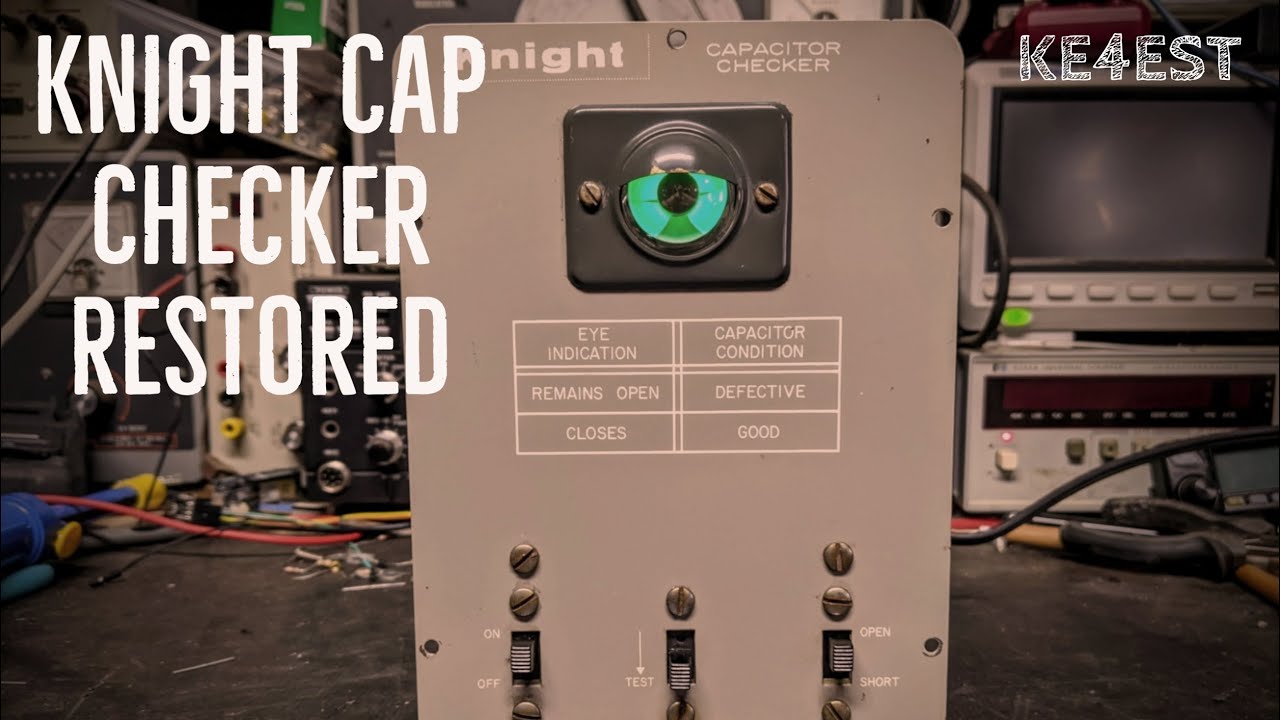
I have a 40 watt Weller iron upstairs, but it was slightly more expensive than the $1.15 they list. The core of the circuit is a Hartley oscillator formed by L-2 and V-2, which is the 6C4 triode tube. K4EST explains some of the RC side during his restoration videos, which are far more comprehensive than what I’ve done and well worth watching.
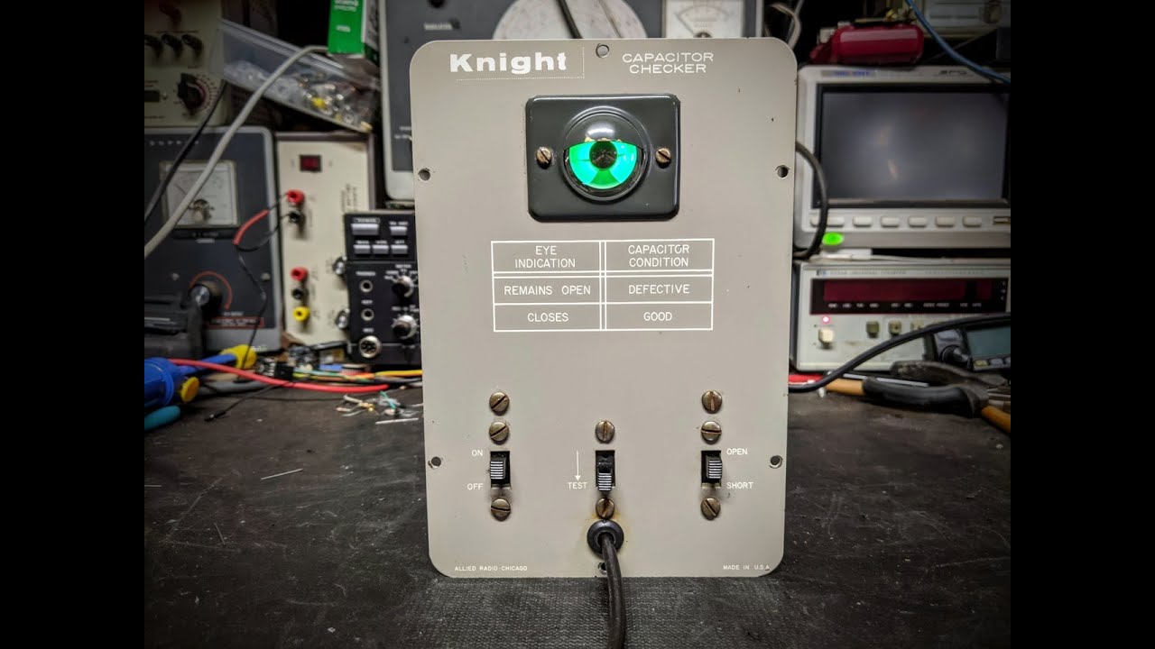
From what I can gather from the manual and videos, these Knight capacitor checkers were originally sold as kits
by Allied Radio out of Chicago. There is no model number or date code, but the manual seems to have been published
in 1955. Some of the capacitors look like they are newer than that, and there were a few leftover leads on the one
of the terminal strips, so I suspect work has been done in here before. I wasn’t able to find a datasheet on the
larger MIEC electrolytic, but I found an Antique Radios post
that says the ETR MET 104K630V uses the K to indicate a 10% tolerance part, so that had to go. I checked Mouser for
parts and found all of the resistor values in Vishay’s CMF Industrial range
with 1% tolerance and the promise of PPMs.


This chassis is pretty open, with only two tubes and a couple of diodes. It only took a few hours to remove, test, match, and replace the passive components. I spent more time fighting the line cord and grommet, which are always a size too small for the loose-end cords I have on hand. The original line cord was not polarized or fused, as usual, so I added a glass fuse. These green fuse holders that I picked up a while back are turning out to be more help for old tube chassis than protoboard, where their pins don’t fit correctly. One of the posts I found mentioned that a grounded line cord will not work for this, but stopped just short of explaining why. I tried both with and without, and am still not sure if it made a difference. It’s possible my isolation transformer was contributing to the confusion, but there does seem to be an audible hum without the ground.


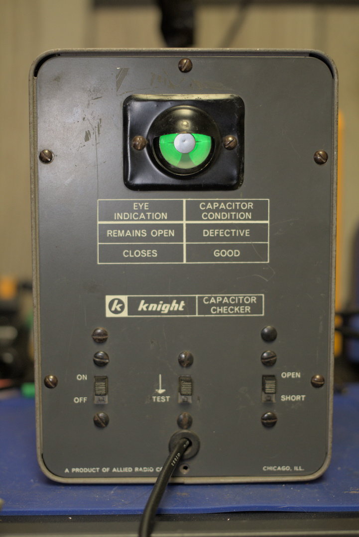
Looking at the manual’s adjustment procedure, it says the oscillator should be “approximately 20mc,” and uses the eye tube’s shadow as the tuning indicator. I’m not sure what shape this tube is in, but the maximum shadow appeared right around 24MHz. At 20Mhz, the eye was entirely closed, so that seems to be very approximate or my scope is impacting the frequency. I don’t fully understand the math for these quarter wave stubs yet, because by my calculations, 24MHz would need a stub closer to 2 meters. This lead is supposed to be 48" plus internal wiring, which I confirmed with a ruler. After finishing the adjustments, the eye responds well to open and shorted leads, but I don’t have any known-bad capacitors to test with.
Replacement Parts Installed
| Component | Schematic | Part Used | Replacement | Original | Capacitor Test | Notes |
|---|---|---|---|---|---|---|
| C1 | 20 MFD 150V, electrolytic | Vishay/Sprague TVA1508-E3, 20uF 250V | 20.13 uF | 18.315 uF | good to rating | |
| C2 | .0015 MFD, ceramic disc | Vishay/BC Components AY2152M31Y5US63L7, 1500pF X1Y2 | 1500 pF | 1115-1133 pF | good to rating | steadily declined while on DER meter |
| C7 | .1 MFD 200V, paper | Vishay/Roederstein MKP1839410634HQ, .1uF 630V | 101.92 nF | 103.40 nF | some leakage above 250V | not a paper/wax |
| R1 | 47 ohm, 1W | Vishay/Dale RS01A47R00FE70, 47 ohms 1% | 47.03 ohm | 53.23 ohm | ||
| R2 | 10K ohm, 1/2W | Vishay CMF6010K000FKEK, 10K ohms 1% | 10.013K ohm | 10.374K ohm | ||
| R3 | 47K ohm, 1/2W | Vishay CMF5547K000FHEK, 47K ohms 1% | 47.24K ohm | 52.99K ohm | ||
| R4 | 470K ohm, 1/2W | Vishay CMF60470K00FHEK, 470K ohms 1% | 469.9K ohm | 546.1K ohm | N/A | tested after removal, could have been R5 or R6 |
| R5 | 470K ohm, 1/2W | Vishay CMF60470K00FHEK, 470K ohms 1% | 470.5K ohm | 522.3K ohm | N/A | tested after removal, could have been R4 or R6 |
| R6 | 470K ohm, 1/2W | Vishay CMF60470K00FHEK, 470K ohms 1% | 470.4K ohm | 560.9K ohm | N/A | tested after removal, could have been R4 or R5 |
C7 was not a paper/wax and appeared to have been replaced at some point with a yellow barrel marked ETR MET, which
should be polyester film. That one tested the weakest, despite having the highest voltage. The ceramic disc was not
great either, the best reading I could get was -24.5% from the schematic, but that may be influenced by the low value.
Looking at the schematic, C2 seems like the most likely candidate for a safety capacitor, and appears to filter the high voltage line to the chassis. Adding an additional safety capacitor across the input side of the transformer seems like it could mess with the oscillator, so I skipped that for now. I measured the high voltage winding at 156.9V with a supply of 125VAC, although someone’s pencil notes in the schematic suggest 170V. The 6V winding to the tubes measured 6.663V.
I like the Vishay parts so far, accuracy seems very good, but some of the ATOM capacitors are pretty expensive. The CMF Industrial range of resistors has a lot of useful values at 1%, and even has a few at 0.1%. I’ll have to see how they hold up over time.
Original Parts Retained
I was not able to reliably test the remaining mica capacitors in-circuit:
- C3: 25 MMFD, mica
- C4: 7-45 MMFD, trimmer
- C5: 200 MMFD, mica
- C6: 250 MMFD, mica
Both tubes and their sockets were kept (V-1 and V-2), along with the transformer (T-1), selenium rectifier (CR-1), and crystal diode (CR-2). I may be able to test the latter, but am not equipped to test the tubes on their own.
There are a few coils, one for the oscillator (L-1) and a pair of chokes (L-2, L-3) according to the schematic. These all appeared to be in good shape, and I’m not sure what to look for, so I left them as they were.