This was the first Micronta analog multimeter that I picked up, but not the last - not even the last 22-204C to date. It was sold as a parts unit for the knob or gauge, thanks to some pretty serious battery rot. I wasn’t sure if it would be repairable, but I was already buying a few other items from the seller and it was $9.99. That’s a pretty steep discount over the original price of $29.95, back in 1974.
When this meter was originally made, it was one of the better meters in the range. I have since filled in the low end with a 22-027, which is the smallest meter I have, and a pair of 22-201s. The next one I’d like to find is the 22-205 flagship model, with the 100M ohm range.
Interestingly, the lowest-spec meter in the range, the 22-027, is the only one to mention using “precision 1% tolerance resistors throughout.” Based on the band values, both of my 22-204s have a mix of 1% and 2% resistors, but I’d rather replace the resistors with at most 1% when the right values are available (and outside of tuned circuits). They all advertise accuracy in the ±3% range, and the good one seems to be pretty close on the voltage ranges. The resistance ranges are further out, but that might be due to battery voltage, I need to test it with the power supply as a source.
The battery contacts were beyond salvaging, and I had to pull them out with pliers. After removing the gauge, I soaked the body and circuit board in dilute white vinegar. There was enough crust that I had to change the vinegar a couple times, then took a soft toothbrush to the bakelite case and board itself.
Two traces on the voltage doubler and adjust board appeared to be rotten through, but read as negligible resistance on my Fluke 8840A, within a margin of error from the leads alone. There were also a pair of resistors on the main board that had battery juice drip onto them, and will need to be replaced, but read close enough for now.
Much of the wiring harness had to be replaced, the contact points had decayed to the point that it broke off while I was removing the board. I put in soft silicone wire and a few dupont-style pin headers to help simplify future repairs to the board. I would like to try replacing all of the resistors in one of these with the fancy 0.1% Vishay parts and see where the accuracy ends up. They would probably cost more than the original unit, but a extremely accurate analog meter would be fun to have.
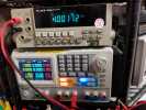
After some cleanup and basic repairs, including a few solder-reinforced traces on the adjustment board, the meter went back together with only minimal difficulty. The self-tapping screw that holds the adjustment dial onto the body was loose when I removed it and needed to be replaced with a larger thread size, which seems to be holding well. Without replacing any of the passive components, the voltage accuracy is not great on the leaky meter (right side):
My other 22-204 is much more accurate, within the original specs on all of the ranges I’ve tested. It has a little bit of rust around the 9V battery contacts, but nothing serious and puts out almost exact battery voltage in resistance mode. These meters have two different batteries for extra fun when it comes time to clean them out. In normal operation, it seems like the 9V battery is used for the 10K ohms range, which I would guess is to provide more current consumption and easier reading.
That makes sense when you consider the schematic of the unit, where both batteries are tied to a common line - except that is not the common ground plug, so if you measure voltage across the leads in resistance mode, it will actually be negative. For a resistance measurement, I guess that wouldn’t matter much, but I’m not sure why the circuit ended up like that. It’s possible that it has something to do with the fact only one end of the battery can be disconnected, and putting the high side on the normally-connected line would effect some other components. Regardless, it means that switching ranges can suddenly put a negative voltage on the common lead, so probably best to remove them while doing so.
The first unit did not come with a manual, but I was able to find a schematic. It uses a symbol that I was not familiar with or able to find in any reference, even checked with a friend whose dad builds tube gear. Based on the placement in the circuit, shape of the leads, and markings on the part itself, which have a triangle symbol and read 7K220, I believe these are varistors acting as high voltage shunts from the DC and ohms ranges to common. There does not appear to be a path from the AC ranges through either SA1 or SA2, unless I am missing something.
The second unit came with a box, manual, and leads. The leads are in pretty good shape and fairly soft, but the red lead’s banana plug fits loosely and will fall out of the meter with a slight tug, so I will need to fix that up. The leads for the 22-027 were also in fairly good shape, but only one of the 22-201s came with leads, and they were in terrible shape. Luckily, normal banana plugs are a good fit for the 22-204, and the good unit will be a nice isolated meter for some of the absurdly high voltages that my capacitor testers can put out.
Since picking up the first 22-204C, I have acquired a few other examples of their analog meters, and will probably find a few more.


